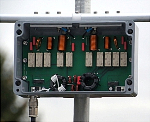
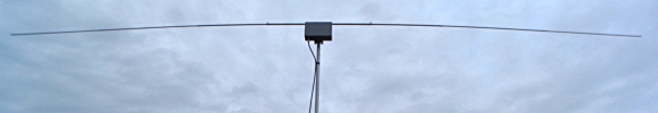
Outdoor-Unit (opened), HF-connector N
Here the symmetric structure is clearly visible
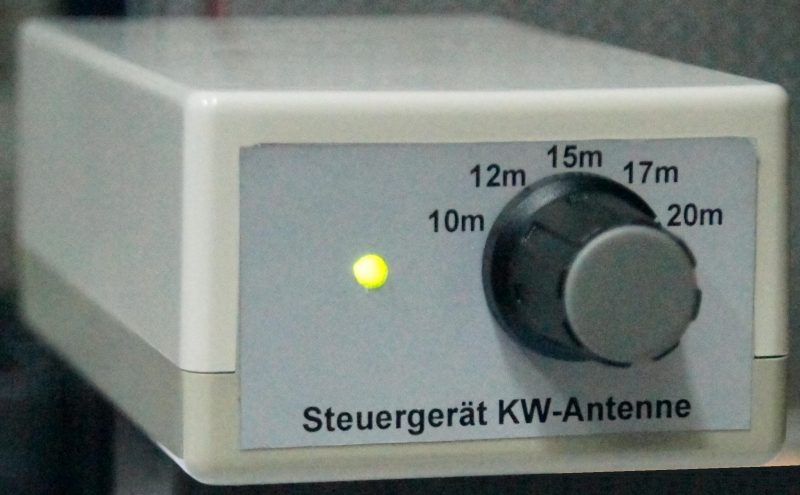
Control-unit of the sw-antenna
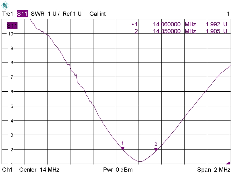
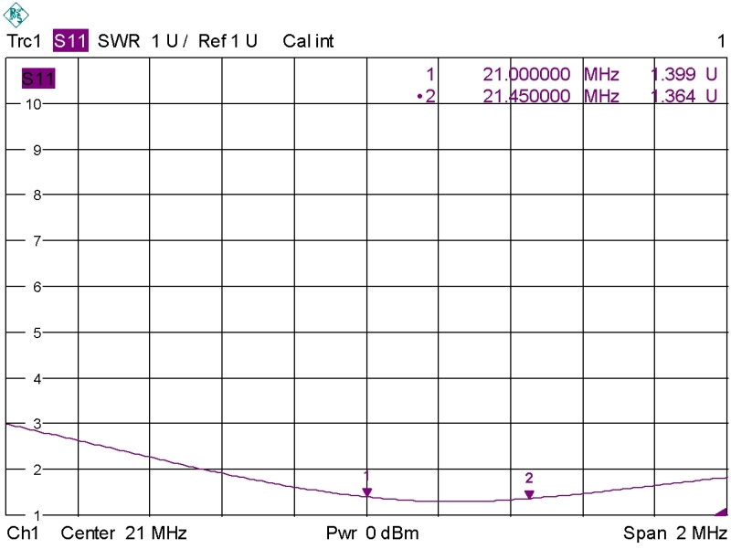
SWR-curve 20m band
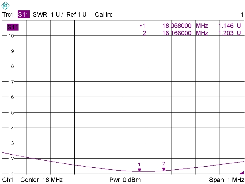
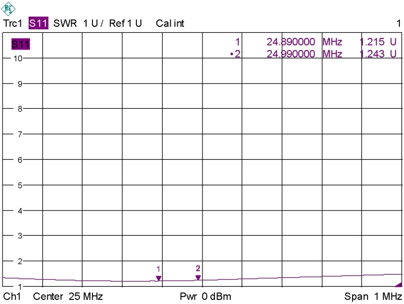
SWR-curve 17m band
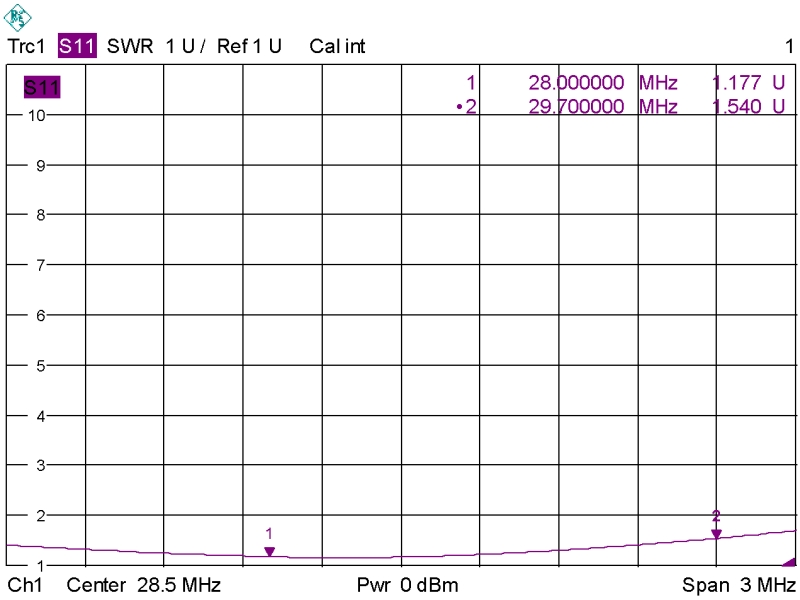
SWR-curve 15m band
SWR-curve 12m band
SWR-curve 10m band
This small Rotary dipole consists of the outdoor unit and the control unit. In the outdoor unit the matching network is constructed perfectly symmetrical to use the "poorness of noisance" which can be reached with a balanced antenna.
The switching of the individual bands is done with sealed relays, which also function as decoupling-elements from the "other" bands.
In order to adapt non-resonant antennas usually transformation networks with Pi-arrangement are used. However, in order to keep loss of matching as low as possible, with this antenna the complex base impedance for the selected band is implemented with a single element per side, and thereafter, the complex base impedance is transformed by a low-loss transformer to 50 Ohms real impedance.
Thus, the SWR curve, seen over the frequency, becomes somewhat wider than with other transition networks. A built in balun behind this with more than 30dB common mode attenuation provides a "cold" coaxial cable, which is becoming more and more important not only for sending, but also for reception. Just think about the broadband noise from various switching power supplies and much more.
Switching of the bands is controlled via the coaxial cable.
In the outdoor unit, the central part of the radiator, which has a length of about 2 x 0.5 m and an outer diameter of 20 mm, is constructed mechanically stable and water-resistant assembled. The rest of the radiator consists of three 1m long tubes, graduated down to 10mm outside diameter. The antenna is small and portable, but yet sturdy.
At the control unit in the shack the bands can be selected by a rotary switch. Without powering the control unit, the 20m band is selected by default. A standing wave trap is already installed in the control unit. More information about mantle wave barriers can be found at our website.
The switching signals for band switching are generated in this controller also.
As supply for the control unit you should not use a switching power supply, because the broadband noise generated with the most switching power supplies often causes problems in the receiver despite good choking.
At the operating unit different sockets are used as RF connectors. For connecting the transceiver a BNC connector is installed; for connecting the antenna, a N terminal jack is used. Since the case is very small, no SO-239 connectors could be used. For suppression of standing waves a standing wave trap is already installed in the control unit. The connector for the power supply is included in the purchased parts package.
As a coaxial cable to the antenna we always recommend RG-214, RG-223, Aircell 7, Ecoflex 10 or similar, as these cables have a very good shielding capacity.
Cable such as RG-213 or RG-58 with a shielding capacity of 50dB at 14MHz should no longer be used because of the ever increasing broadband noise nowadays.
Outdoor-Unit (opened), HF-connector N Here the symmetric structure is clearly visible |
Control-unit of the sw-antenna |
SWR-curve 20m band |
SWR-curve 17m band |
SWR-curve 15m band |
SWR-curve 12m band |
SWR-curve 10m band |
|
Specifications: |
|
Outdoor-unit housing: |
Polyester |
Antenna gain on all bands (as a reference a monoband λ/2-dipol in the same building-height is assumed) |
0...-1 dBd |
Maximum power: : |
400 W |
Dimensions of Outdoor Unit (without radiator parts): : |
260 x 160mm |
Weight of outdoor unit (complete with radiator and bracket): |
about 4 kg |
Transport length: : |
1.1m |
HF-connector: |
N-socket |
Maximum mast diameter: |
50mm |
Plastic housing to decouple the input and output connector (standing wave trap installed).
Dimensions (approximate dimensions): : |
150 x 64 x 40mm |
Antenna connection: |
N-socket |
Transceiver connection: |
BNC-socket |
Power supply: |
13...15V / 250mA |
Connection voltage supply (plug included): |
3.5mm barrel connector |